This web page focuses on the software aspects of the OSFI project.
The hardware for this project is designed and manufactured at Sensair which has its own OSFI project web page
including some history and contact info. Also for source code and
binaries see the Sourceforge
project page.
The OSFI project is an attempt to design and develop a set of low cost flight instruments for the use of pilots in all forms of soaring flight ie. sailplanes, hang gliders and paragliders. Open source in this context means that the physical hardware will be available at near manufacturing cost price, and the software will be free. Hardware designs and source code will be freely available to the public.
It is envisaged at this stage that three forms of flight instrument will emerge from this project.
This is a pod that will generate variometer audio and send real time flight data to a PDA. The PDA will then present this data visually to the pilot. PDA software is not at this stage part of this project. PDA hardware is third party and not provided.
This is a very low cost stand alone instrument with a simple
character based LCD display. It will provide a large amount of
functionality but will be somewhat restricted as to how it will present
flight data to the pilot.
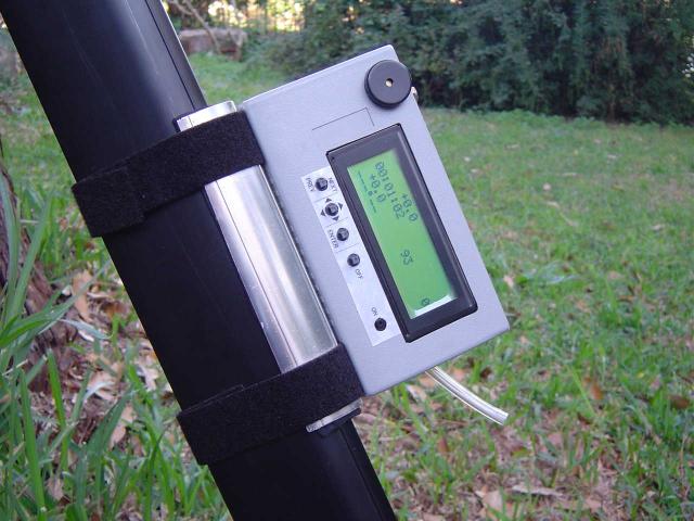
Here is an image of one of the first character based instrument prototypes developed under the project. The hardware has been mounted inside a fairly compact ABS case which is shown attached to a hang glider control frame with velcro straps.
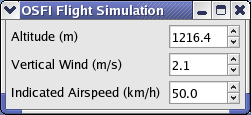
The following are screen captures of the PC GUI application that
simulates the character based instrument in flight. The first
image shows the "Flight Simulation" window which allows the user to
control certain parameters being simulated such as the altitude,
airspeed and the vertical wind speed (rate at which the air is rising or
sinking). These settings determine what the simulated sensor A2D
readings will be to the main part of the program. The altitude in
this window is automatically recalculated each second so that it
simulates the sink rate of the glider according to the other parameters
and the polar of an imaginary glider.
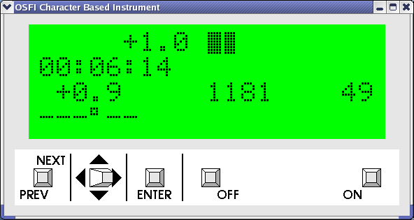
The second image shows the simulated LCD and keypad of the
instrument. Most of the actual code used on the real instruments
runs in the background. The GUI allows the user to see how the
instrument reacts to the Flight Simulation settings and presses of the
joysticks on the simulated keypad.
This is flight instrument similar to the character based instrument,
but with a graphical LCD display, allowing it to present flight data to
the pilot in a more sophisticated and user friendly manner.
The following documents describe the requirements for the project.
The hardware design is described here.
The software design is described here.
The software development environment is described here.